|
Fred Connell Student Blacksmith Power Hammer Whack Whack Calm |
||
|
||
| Other Stuff: | ||
|
-
Rose Engine
|
||
|
OrnamentalRoseEngine.com E-mail: info1@OrnamentalRoseEngine.com |
|
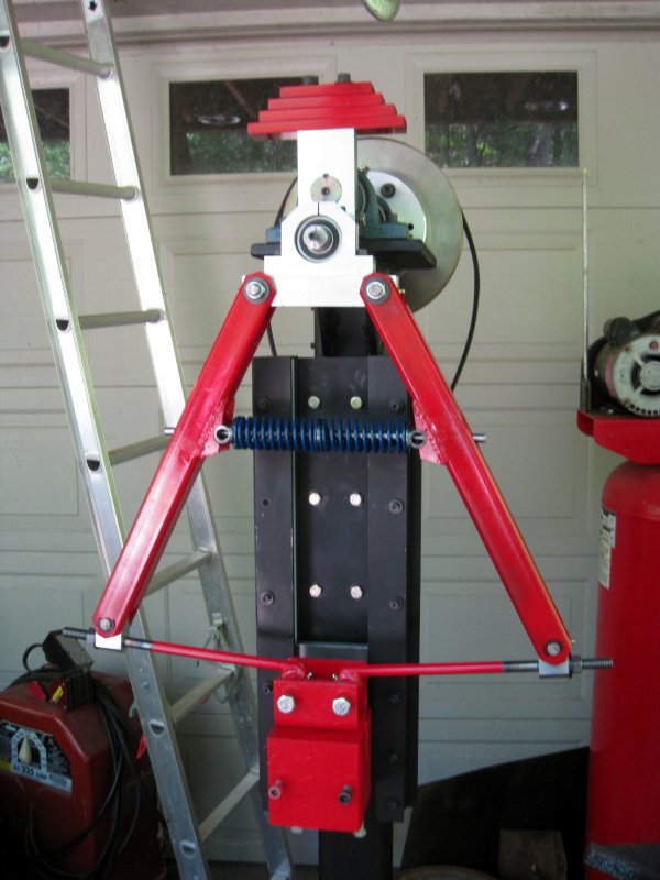
Dupont style linkage assembly
|
Differences from original Dupont design: The crankshaft balance can be easily adjusted by changing the number or combination of counter weights bolted on the crankshaft. The rhetorical counter balance weight is difficult to calculate. After the power hammer is assembled, the counterbalance weight is simple to determine statically. The at rest hammer height over the anvil can be decreased by installing a spacer block between the linkage main bearing and the upper linkage arm support. Or, spacers can be installed under the crankshaft pillar block bearings to increase the distance. The initial design distance is 1.5". Later, I may want to adjust this. Tightening the lower linkage arms increases the spring tension and at the same time decreases the possible hammer stroke per revolution. Design details:The springs are mounted on a shaft which rides in a bronze bushing in the spring end seat. The shaft forces the spring end seat to rotate in the upper linkage arms as the arms move. The springs are not deformed sideways as they are compressed. The springs specifications are 270 pound to compress 1" and each inch there after. These special springs have a longer than normal design compression range. Maximum production compression should be less than 2" for each spring, that is 50% of the springs length. The Dupont linkage is designed such that the spring compression will operate only within the spring specification. At the maximum design compression of the springs they will require 1080 pounds of force. The hammer bearing mount is offset to keep the center of balance of the hammer assembly aligned with the center of the linkage. Hammer energy is directed to the direct center of the hammer die. There will be no twisting forces on the hammer at impact with a direct center impact. The crankshaft and main linkage bearings are a deep grove sealed ball bearings. All other bearings are 841 oil impregnated bronze. Grease fittings are provided were practical. The crank throw radius can be changed by fabricating a new crank arm and bolting into place. A new top link arm block can be fabricated with different dimensions between the top linkage arm bearings. This would allow the head stroke to be changed without changing the spring tension.
Initial testing was at the rate of 3 impacts per second. At rest, the springs are compressed a total of 1.1" inches. The spring specification is 270 pounds per inch with a maximum operating compression of 2" each. So, the at rest spring compression force should be 288 pounds. |

|
OrnamentalRoseEngine.com
E-mail: info1@OrnamentalRoseEngine.com |