|
|
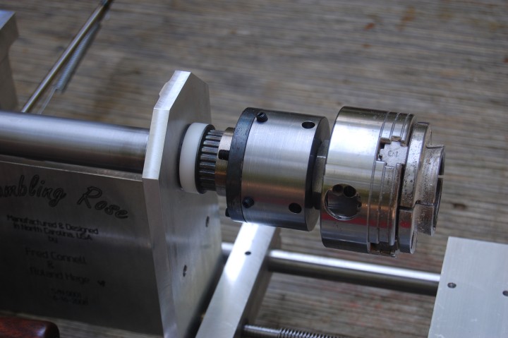
Chuck Adjusting Spider
|
Roland Hege and I have designed, specifically for a Rose Engine, a spindle to chuck adjusting spider for very fine adjusting of the chuck and work to the center of rotation of the rosette cam. This will allow corrections for any of the Rose Engine systems (rosette cam, spindle or chuck) that might not be exactly true with the spindle rotation. When doing very light cuts of a few thousandths of an inch, the work absolutely must rotate true or the error will obvious in the work. This is especially true when making light cuts in plastic or metals. The chuck spider allows adjustment between the spindle center and the work center in all three axes. An 8.5 degree turn of an adjusting screw moves the spindle 0.001". So, fine adjustment is very easy. It does not take but a few thousandths run out anywhere in the Rose Engine from the cam to the workpiece to show in delicate cuts. The chuck adjusting spider and timing belt drive were heat shrunk onto the spindle. Brass tipped set screws are used in the spider to keep from damaging the adjustment surfaces and ensuring smooth accurate adjustments. The spindle head is threaded 1" x 8 tpi common to wood turning lathes and has a Morse taper(MT-2) for specialized chuck jigs. The front part of the spider can be replaced with another spider front to change the spider thread size or add other accessories directly to the spider. Several things can cause run out and the effect can be additive:
How to adjust the spider:
The spider can be quickly adjusted if adequate measuring surfaces are cut on the workpiece. First, lock the Rose Engine headstock so it can not rock. The axial adjustment is accomplished with the set screws on the back of the spider and aligns the line through the center of the spindle to be parallel with the line through the center of the work. To accomplish this the workpiece must have a flat surface on the edge of the face of the work to indicate (measure with an indicator). The maximum and minimum values are noted, the indicator is set to "0" at the value half way between and the back set screws are adjusted to the "0" value. The indicator should show the same reading as the spindle and workpiece is rotated with the headstock rocking motion fixed. Second, unlock the spindle and install the cam that will be used to cut the pattern. The radial adjustment is accomplished with the set screws on the sides of the spider and aligns the work center line to correspond to the spindle center line. To accomplish this the workpiece must have a small portion of the outside of the work piece cut as a cylinder measuring surface. While rotating the spindle and workpiece the values of the indicator on the outside of the cylinder for each of the cutting positions (rosette cam valley positions) are noted and the same maximum and minimum procedure as above is used to center the work piece. Now, the workpiece is exactly centered to the cutting action dictated by the rosette cam and any misalignment's are corrected. It takes less time to do than to explain. |

|
OrnamentalRoseEngine.com
E-mail: info1@OrnamentalRoseEngine.com |