|

|
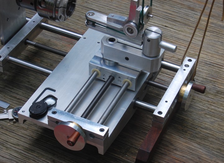
X-Z Compound Table
|
The X-Z compound table was integrated into the structural frame or ways of the RRE, eliminating the need for a table. We used left hand acme thread lead screws so a clockwise turning of the adjusting wheel would result in normal machine tool movement of the compound tables. The 10 threads per inch count of the lead screws result in one complete turn moving the table 0.100 inches. The adjusting wheels have adjustable dials calibrated with 100 divisions per revolution. Each division will move the table 0.001 inch. The round and square tool holders are mounted on a goose neck type of mounting to allow extended horizontal and vertical locations of the cutting tool, keeping the overall dimensions of the Rambling Rose Engine compact. The ways are hardened and ground for accuracy and wear resistance and the tables have precision plastic bearings. Any length ways and lead screws could have been used for either the Z-axis or X-axis compound tables.
Note X-Y-Z-axes: |

|
OrnamentalRoseEngine.com
E-mail: info1@OrnamentalRoseEngine.com |