|
Overhead crane and cutter drive system
|
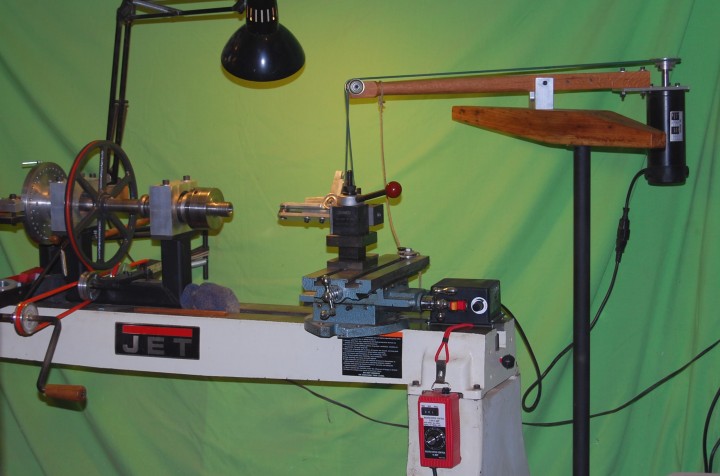
The overhead cutter drive for my Rose Engine was originally supported with a cross member and two vertical tubes that were bolted to to each end of the Rose Engine bed legs, looking much like football goal posts. To minimize any chance of overhead cutter motor vibrations, I decided to remove the overhead drive from the Rose Engine lathe bed altogether. The crane head and overhead motor drive form an articulating arm that will allow the end of the motor drive to be located wherever the cutting frame is needed. A cast iron heavy truck wheel is used as a base for the overhead drive crane. The bolt head is cut off of a 8" long one inch diameter bolt. The remaining threaded pin is held in one of the lug holes of the truck wheel with two nuts, leaving about 5" of the 1" diameter pin sticking up. A 1" ID iron pipe column, long enough to locate the crane head at the proper height, is slipped over the pin. I used a piece of aluminum flashing as a shim-bushing to get a good slip fit. I made the crane head from a beautiful piece of wormy hickory. 1/4" holes 2" OC were drilled in the top of the crane head for locating the overhead drive yolk pin along the crane head arm and a 1" diameter hole was bored for the crane head pivot pin. The pin has a press fit into the hickory crane head. Five inches of the pin extends below the crane head and is inserted in the upper end of the 1" diameter pipe column. The crane head can rotate 360 degrees. This is a very sturdy arrangement, quick to build and relatively inexpensive. |

|
OrnamentalRoseEngine.com
E-mail: info1@OrnamentalRoseEngine.com |