1st & 2nd Generation
Rose Engine

-Fabrication notes 1/27/10
   Prototype:
- Prototype Rose Engine
- Rubber & rosette cam
   Construction:
- Turning the index wheel
- Drilling the index wheel
- Cutting a Rosette cam
- Fabricating T-nut
- Rubber assembly
- Spindle & bearings
- Pivot axle & bearings
- Spindle & frame
- Index wheel installed
- Rocking stop arm
- Rose Engine ready to test
- Chuck holding work
- Turn aluminum on wood lathe
- Hand crank and handle
- Threading follower
- Copy a cam
- Drilling a cam
- Finished rosette cam
- Router assembly
- Boring bar cutters
- Chuck adjusting Spider
- Overhead drive
- Cutting frame
- Rose Engine with router
- Overhead crane
- Drilling frame
- Collet Chuck
- Hardinge compound 9/5/11
- X-Z compound ways 12/28/11
- Test results - Gallery
   Notes:
- Description of a Rose Engine
       by Jon Magill
   Other Stuff:
- Rose Engine 3rd generation mobile
- Wood Lathe works
- Shop jigs homemade
- Downloads & plans

OrnamentalRoseEngine.com E-mail:
info1@OrnamentalRoseEngine.com

linear1.jpg 640x388 - 57.7k
Rose Engine & Ornamental Lathe
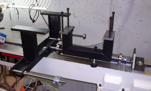
Rubber assembly, spindle frame, pivot axle, linear and ball bearings.

The ground pivot shaft is pressed in the spindle frame.   Linear ball bearings which ride on the pivot shaft are fitted inside of regular ball bearings to allow the spindle head both rocking and pumping movement on the pivot shaft.   The bearing block mounts are milled flat and drilled and tapped for the bearing cap bolts and alignment pins.   The left bearing block mount is tapped for the rocking return spring and the rocking stop.

Work capacity is 16.5 inch diameter.   Thread cutting capacity is 1.5".

1x3 bar_rust.gif
Rose Engine Rose Engine barleycorn design barley10.jpg 65x65-2.7k
           OrnamentalRoseEngine.com
E-mail: info1@OrnamentalRoseEngine.com