1st & 2nd Generation
Rose Engine

-Fabrication notes 1/27/10
   Prototype:
- Prototype Rose Engine
- Rubber & rosette cam
   Construction:
- Turning the index wheel
- Drilling the index wheel
- Cutting a Rosette cam
- Fabricating T-nut
- Rubber assembly
- Spindle & bearings
- Pivot axle & bearings
- Spindle & frame
- Index wheel installed
- Rocking stop arm
- Rose Engine ready to test
- Chuck holding work
- Turn aluminum on wood lathe
- Hand crank and handle
- Threading follower
- Copy a cam
- Drilling a cam
- Finished rosette cam
- Router assembly
- Boring bar cutters
- Chuck adjusting Spider
- Overhead drive
- Cutting frame
- Rose Engine with router
- Overhead crane
- Drilling frame
- Collet Chuck
- Hardinge compound 9/5/11
- X-Z compound ways 12/28/11
- Test results - Gallery
   Notes:
- Description of a Rose Engine
       by Jon Magill
   Other Stuff:
- Rose Engine 3rd generation mobile
- Wood Lathe works
- Shop jigs homemade
- Downloads & plans

OrnamentalRoseEngine.com E-mail:
info1@OrnamentalRoseEngine.com

Router and cutter -router01.jpg 424x640 - 51k
Custom Rose Engine & Ornamental Lathe
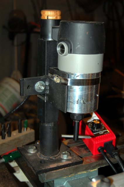
Router, boring bar, cutter and router assembly

The router assembly is made up of the column, column bracket and router bracket. The router can be moved to any height and any angle in the X, Y and Z dimension. The router will fit upside down if you need the opposite rotation. The has 1/2" and 1/4" collets. I find I'm using 1/2" boring bars with 3/16" square high speed steel bits the most. A critical element allowing use of the router is the separate variable speed controler. It allows adjustment of the speed to whatever you want. Without it the router will run much too fast for these boring bars. I run it around 1000 RPM most of the time.

1x3 bar_rust.gif
Rose Engine Rose Engine barleycorn design barley10.jpg 65x65-2.7k
           OrnamentalRoseEngine.com
E-mail: info1@OrnamentalRoseEngine.com