1st & 2nd Generation
Rose Engine

-Fabrication notes 1/27/10
   Prototype:
- Prototype Rose Engine
- Rubber & rosette cam
   Construction:
- Turning the index wheel
- Drilling the index wheel
- Cutting a Rosette cam
- Fabricating T-nut
- Rubber assembly
- Spindle & bearings
- Pivot axle & bearings
- Spindle & frame
- Index wheel installed
- Rocking stop arm
- Rose Engine ready to test
- Chuck holding work
- Turn aluminum on wood lathe
- Hand crank and handle
- Threading follower
- Copy a cam
- Drilling a cam
- Finished rosette cam
- Router assembly
- Boring bar cutters
- Chuck adjusting Spider
- Overhead drive
- Cutting frame
- Rose Engine with router
- Overhead crane
- Drilling frame
- Collet Chuck
- Hardinge compound 9/5/11
- X-Z compound ways 12/28/11
- Test results - Gallery
   Notes:
- Description of a Rose Engine
       by Jon Magill
   Other Stuff:
- Rose Engine 3rd generation mobile
- Wood Lathe works
- Shop jigs homemade
- Downloads & plans

OrnamentalRoseEngine.com E-mail:
info1@OrnamentalRoseEngine.com

Spindle to chuck alignment spider -spider01.jpg 640x426 - 69.4k
Custom Rose Engine & Ornamental Lathe
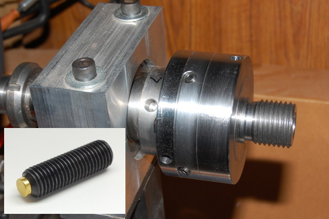
Spindle to chuck alignment spider

The chuck Spider allows adjustment between the spindle center and the work center in all three axises. An 8.5 degree turn of an adjusting screw moves the chuck 0.001 thousandth of an inch. So, fine adjustment is not at all difficult. It does not take but a few thousandths of an inch run out anywhere in the Rose Engine system, from the cam to the workpiece, to show in delicate cuts.

Brass tipped set screws are used to keep from damaging the adjustment surfaces of the Spider and ensuring smooth adjustments.

1x3 bar_rust.gif
Rose Engine Rose Engine barleycorn design barley10.jpg 65x65-2.7k
           OrnamentalRoseEngine.com
E-mail: info1@OrnamentalRoseEngine.com